(This is what I did to get it working with the Kamstrup Omnipower as a Radius customer, Danish Power Company)
Over the years as the kids have gotten older, our electrical bill has just gone up and up, and I have been wondering what and when we were using all that power.
My initial setup looked like this.
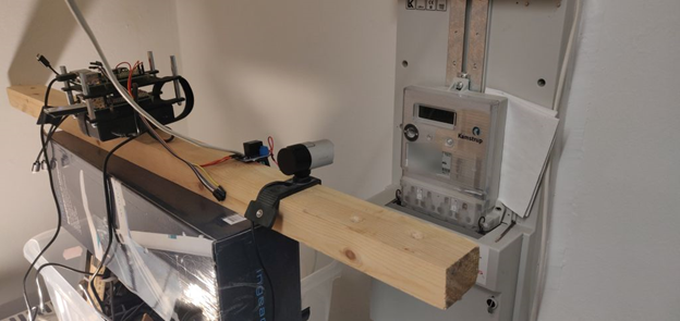
A Raspberry Pi connected to a webcam and a relay to turn on a little LED so the camera could read the LCD when the lights were off. Then sending the pictures to Azure to do OCR to get the reading of the display so that I could measure power consumption over time.
(This was more to play with IoT than anything else, and the WAF was very low)
I Denmark, it has been mandated by law that everyone should have a new smart “Power meter” installed one that can report power consumption hourly, this way there can be differentiated prices on electricity during the day.
When had ours replaced I signed up for an electricity provider that had a fancy app, that would show me hourly usage, but I soon realized that it took them more than 1 day to get the data into the app, and I had hope it would be near real-time ☹
Looking at the new power meter I saw there was a slot in the top for a HAN module, so I started looking around for a HAN module, and only found one called Smart-me, which required me to buy a relatively expensive module (120€) and it connected to a cloud service which I assumed I would have to pay for as well.
I started researching different forums and realized that by law the electrical companies have to provide a way for consumers to read their meters electronically (It did not state that it had to be easy to do it)
So I started looking around and found that Asbjørn (https://github.com/Asbjoern/Kamstrup-Radius-Interface/) had already done most of the hard work, so I tried to get his solution to work, but to no avail. (Sometimes these cheap china boards can be a little finicky)
So I decided to re-write the Arduino sketch that Asbjørn had written, and make it a little simpler (No webserver, mDNS, fileupload etc).
What makes this a little hard is that the data is encrypted, and you need to get your (de)encryption keys from Radius (I do not know how this works with other companies).
With Radius you have to ask for the “DIY” keys (DLMS/COSEM). This means you get 2 keys instead of 1, which is used for the HAN module.
Your meter also needs to have a special firmware, which is supposed to be rolled out to everyone by summer 2020, but when you ask for the keys, I assume the validate you have the correct firmware.
The new firmware outputs the measurement data every 10 seconds to the serial pins behind the “blinder” on the top of the meter
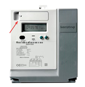
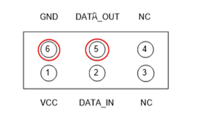
Under that you will find 6 pins in the upper left corner, and we will use Pin 5 and 6, which are “Ground” and “Data_OUT”
I received my encryption keys in an email after about 5 days, the email also contains a very basic description of how to decrypt the data.
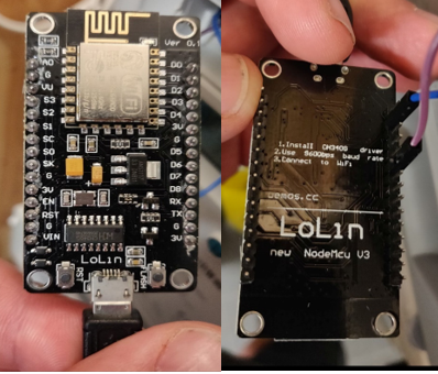
Now I had my keys and was eager to get started so I went and got my 2$ Lolin NodeMCU v3 , and hooked it up to my computer via USB.
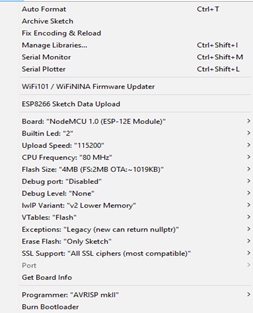
In the Arduino IDE I connect it as an “Node MCU 1.0 (ESP-12E Module)
As stated above I tried to use Asbjørn’s code directly, but for some reason I could not get the MQTT part working.(Also be aware that the code is in the development branch)
It simply did not connect to my mosquito MQTT server, which I run as part of my Home Assistant setup
I decided to try and simplify Asbjørn’s code as much as possible to suit my needs, Read sensor data -> decrypt sensor data -> send sensor data to MQTT server.
I’m not going to go through all the code here, but one thing to notice is that we have to connect to the Power Meter via a serial connection, and the NodeMCU has 2 serial ports that are available, one is usually used for debugging and then we can use UART1 to connect to the Power Meter.
Serial.begin(2400, SERIAL_8N1); Serial.swap();
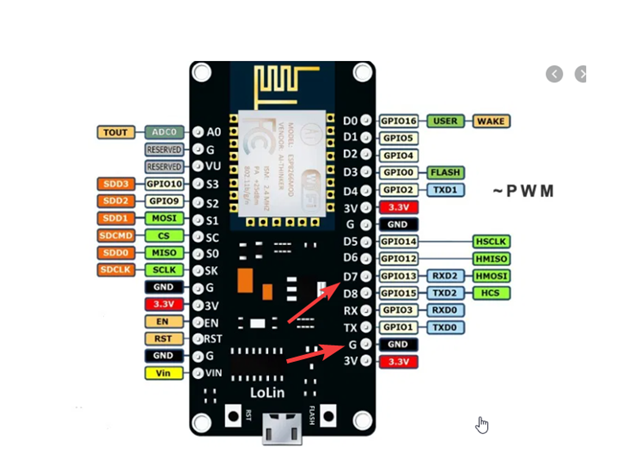
First we set the Serial Port configuration, and then call Serial.swap(); which remaps the UART0 ports from GPIO1 (TX) and GPIO3 (RX) to GPIO15 (TXD2) and GPIO13 (RXD2), from looking at the schematic below we then need to use “D7” to connect to the (TX) port on the Kamstrup Meter (Pin 5)
You need to change the following in the file before you can use it
- ssid
- password (wifi password)
- mqttserver
- mqttPort
- mqttUser
- mqttPassword
- mqtt_topic
- conf_key (Key from Radius)
- cont_authkey (Key from Radius)
(This is very much a v0.1 release, I will move passwords etc into a separate file later.)
When the sketch is successfully loaded, you can connect the NodeMCU to your power meter and power it on, it should connect to your wifi/MQTT server and start receiving data from the power meter, then decrypt it and send the data to your MQTT server. You can verify that it connects to wifi and MQTT from the serial monitor in Arduino.
You can find the code here: https://github.com/Claustn/esp8266-kamstrup-mqtt
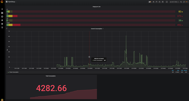
I the following post I will look at getting that data from MQTT into InfluxDB and use Grafana Dashboards to monitor your power usage.